Data management and a workpiece model
ESR2- INTEGRATING MATERIAL PERFORMANCE
AUTHOR: Tom Svilans
January 8, 2017.
I have been meaning to post about this for quite a while but haven’t gotten around to it. What follows is a little update about the computational side of things and what sort of strategies have been employed to manage the various levels of data between design, rationalization, and fabrication. The development has been piggy-backing on the design of a model (or ‘demonstrator’) done in conjunction with Paul (ESR6) as a way to see how our work can start to interface with each other’s workflows and other external things.
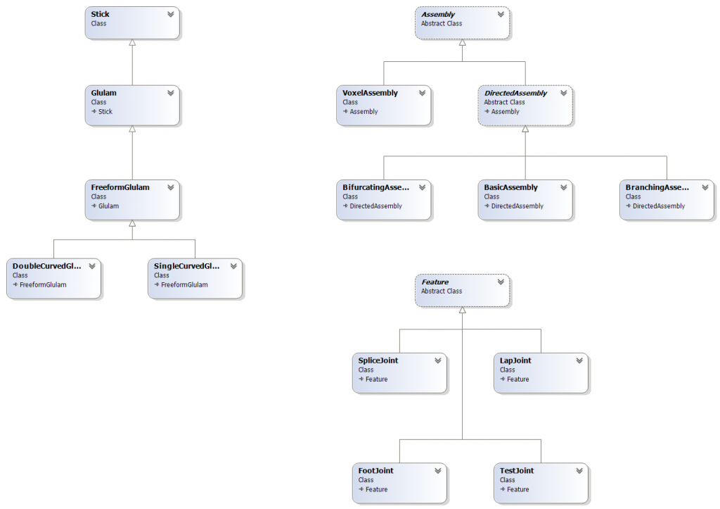
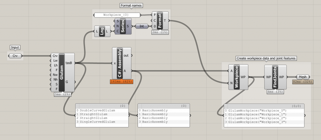
As mentioned in a previous post, I have started to implement a kind of ‘ecology’ of parts and types that seem to come up again and again. Specifically, it starts with categorizing the most basic types of laminated products and the builds upon that by defining various types of ‘assemblies’ which are composed of these basic types, in various arrangements. These are developments from some of the models built in the earlier workshop with CITA Masters students as a way to encapsulate and formalize those experiments into usable, extensible tools for future use. Building these class families has allowed much more freedom and simplicity in the subsequent interfaces and has generally kept headaches to a minimum. For example, a single factory constructor can be used to generate the appropriate type of object depending on the input data, meaning all the checks, validations, and specializations are the constructor’s responsibility, keeping all of those problems in one place and keeping the interface clean from too much redundancy and repetition.
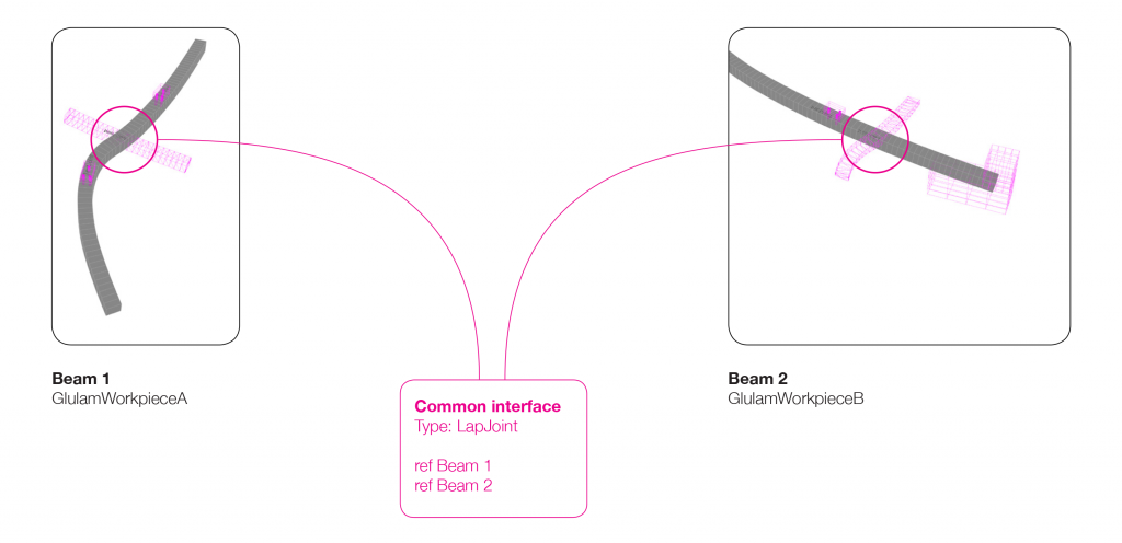
Anyway, long story short, I’ve implemented the basic types (Glulam), some assemblies (Assembly), and joints (Feature). The Feature objects contain all feature- / joint-related data such as work planes, feature geometry, and references to the linked Assembly object(s). For example, a joint between two structural members (Assembly objects) is a Feature that holds a reference to both members and is responsible for the geometric resolution and toolpath generation for itself. In this way the mediation of joints and common features between members is delegated to the joint object itself, not the two Assembly objects which hold a reference to it. This prevents either Assembly object from having outdated or misplaced data about a particular connection. When an Assembly object needs information about a particular joint, it calls the Feature object, which then is responsible for figuring out what goes where and which member gets what information.
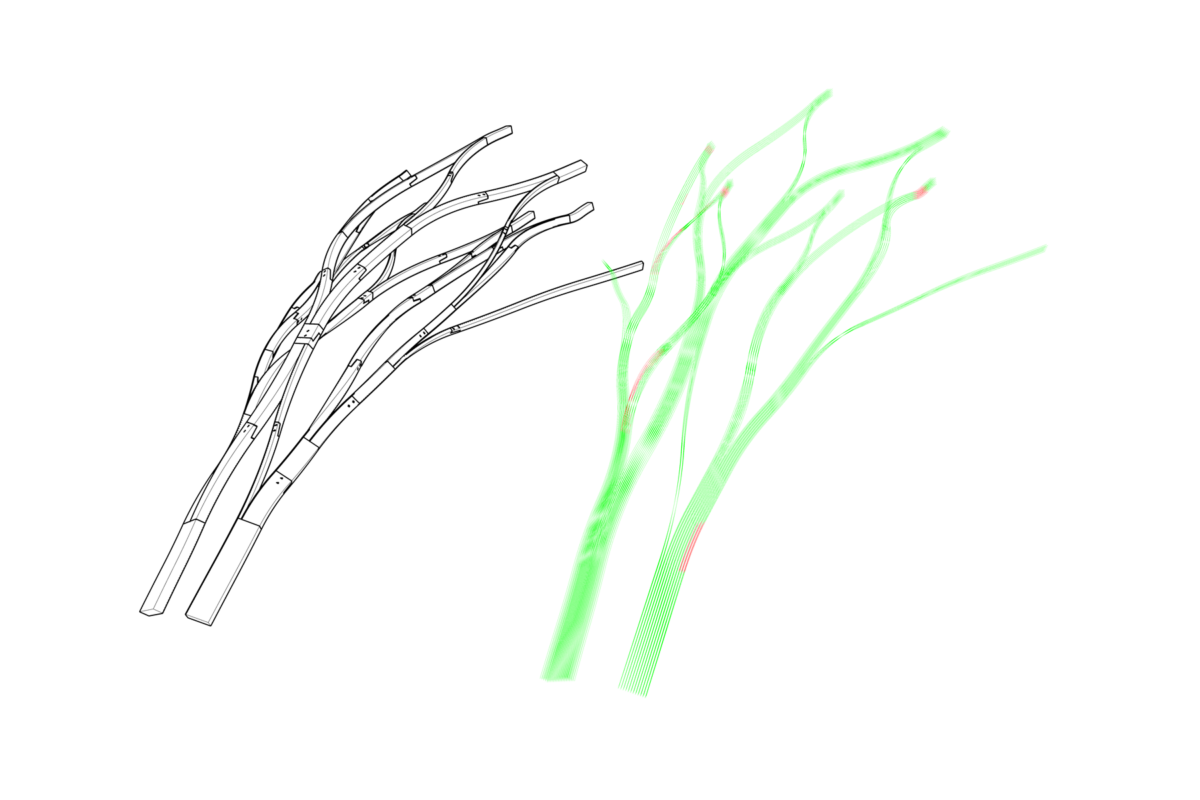
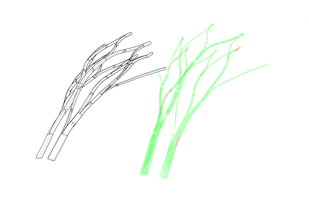
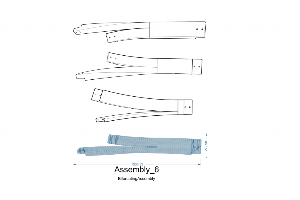
The model we are working on will test this – though so far it seems to be working quite well – and I’m sure there will be adjustments, but at the moment it provides a good platform to extend and build upon for developing more complex assemblies and interfaces between assemblies. A recent change was done to allow different assemblies to have multiple directions: before, a DirectedAssembly was an assembly with a single, distinct direction vector / curve, which made it easier to plot intersections and provide notions of ‘width’ and ‘depth’ against this single ‘centreline’. This all fell apart once the idea of a bifurcating assembly was introduced – a 3-way member – and speculating about other, more complex assemblies. The gradient between glulam and crosslam – beams becoming panels and vice versa – would also call for more nuanced implementations of directionality and such. Another quick thing to note is that, although all the images show mesh representations of the laminated assemblies, all meshing is generated on-demand from drive geometry that is more abstract – i.e. the same drive curves and geometry are used to produce toolpaths as well as display meshes. This sort of ‘need-to-know basis’ greatly speeds things up when working with larger networks of these assemblies.
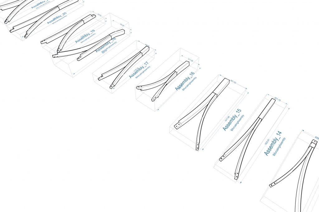
All in all, good progress on the data management front and shots of the model-building will follow. Building it will be a challenge, and I am confident that it will not turn out as expected. There are many individual elements with very aggressive twisting and double-curving, and many opportunities for springback, so we will hopefully have a better understanding of how these can be dealt with and integrated into the workflow once we’re done wrestling with it.
Finally, relating to the whole conversation about data transfer and embedding within models, something I’m keen to look into after this phase is BTL. Instead of re-inventing the wheel, perhaps it may be good to look into aligning the workpiece model I am developing with other efforts to open up communication in fabrication pipelines. At the very least, it would provide a much more complete library of joints and machining operations to play with, and we could see what potential for extension or adaptation there is. On that same note, I’m also really keen to engage with Timber Code and Design-to-Production more about this aspect – how their models organize all the meta-data and non-geometrical information, and how all of that is kept intact from the design model up until the wood shredding begins.