Talking models
ESR2- INTEGRATING MATERIAL PERFORMANCE
AUTHOR: Tom Svilans
July 27, 2017.
Well, it’s been a long time!
In the middle of May, I wrapped up a very enjoyable and productive 2-month secondment at Blumer-Lehmann, down in the rolling Swiss countryside near St. Gallen. Sunshine and snow were both abundant. I will make another post in more detail about the happenings and developments there (and perhaps some holiday photos) and won’t go into it now, save to say that it was a great opportunity to test out some ideas, prototype some bits of hardware, and generally become more familiar with the processes and people behind the top-notch work that goes on there.
Lately, I have been revisiting the models and workflows behind the mysterious demonstrator that I collaborated with Paul on from this past winter – which still hasn’t materialized in its entirety for a variety of reasons. Bits and pieces were made, and the modelling and information-generating workflows were mostly there, but in the end, the largest barrier was the lack of a suitable pressing method for these ‘bifurcating blanks’ and then both of us taking off on our respective secondments. One of the issues with the earlier workflow – at least on my side of things – was that it too often confused the notion of what the design object is and what the production object is. In this case, the experimental glulam blanks were also the finished architectural components, which presented all sorts of problems for forming and the final quality of finish. This meant that the geometry of the blank was bound at the hip to the design geometry of the structural elements, which is not always the case. The ideal scenario is for the blank to match the design geometry as tightly as possible – for obvious structural and aesthetic reasons, to start with – but this is not always practical when factoring in the production capacities at hand and the added burdens this can place on the process.
To keep a long story short, revisiting this earlier workflow resulted in a decoupling of these two aspects: a variety of blanks and blank-making methods that can fit to a particular design geometry, depending on how crucially the wood needs to be aligned with the design geometry. This shifts the focus from trying to make double-curved and twisted glulam blanks easier to produce – which is already being done very well, as seen in the production halls of Blumer-Lehmann – to perhaps some of the other speculative blank types I explored last fall, such as the voxelized types, which looked at how to approximate free-form blank geometry using simple methods to minimize waste and increase the material stability of the blank. What this also points to is that the fit between design object, architectural and structural demands, and the material reality of the forming and fabrication process is much more of a fluid negotiation, where not everyone always goes home happy.
On top of all of this, the multi-scalar aspect of the workflow has also been on my mind quite a lot, and I’ve started implementing some ideas that have been kicking around my head in terms of realizing this ‘ecology of models’ more robustly and completely. It’s precisely this mediation and chitchat between different stages, scales, or domains which forms the link between design and production, which is something fundamental to the whole project. As such, the variety of models is being delineated more clearly, and I’ve been thinking about some possible mechanisms for communication on a practical level.
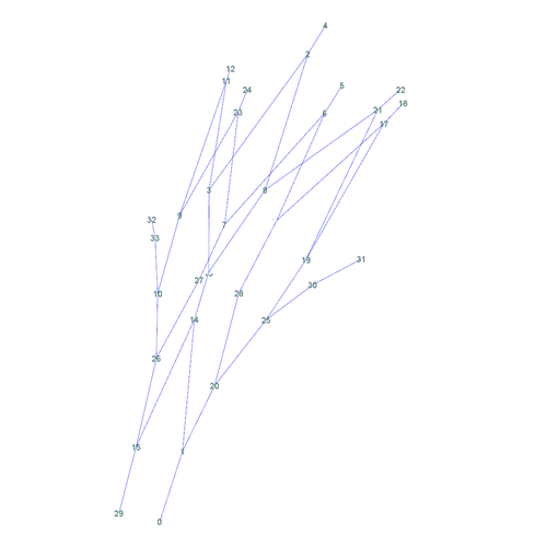
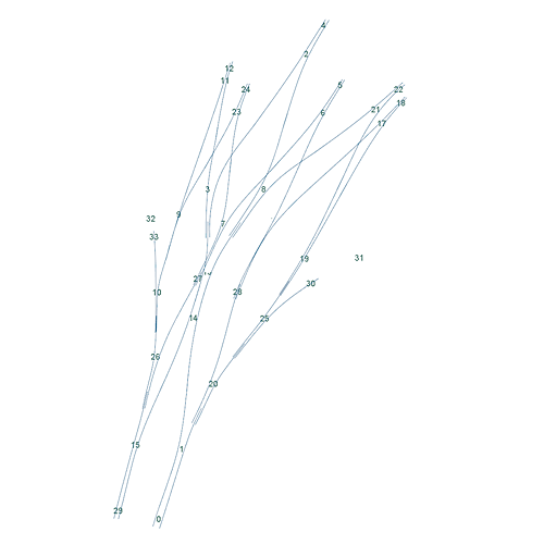

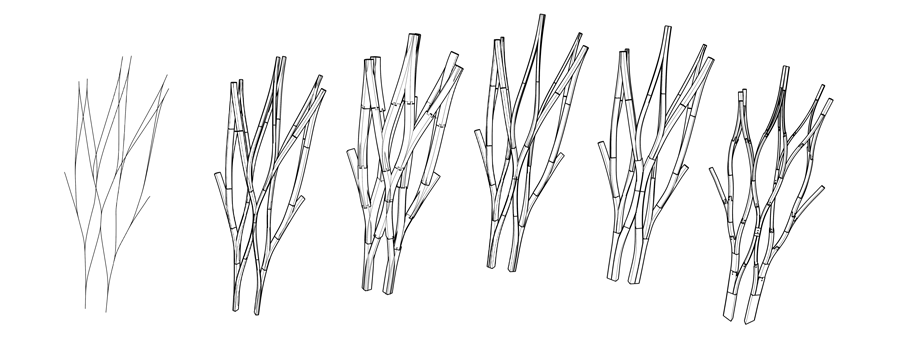
What these snapshots show are the different levels that consitute the design-to-fabrication workflow:
- Figure 1 shows the completely abstract network topology model. It is spatial – each node is at a particular point in space – but very gestural and shows more intent and strategy than tectonics.
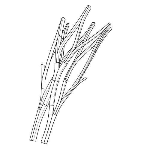
- Figure 2 turns this topology model into flow lines that could be matched with bent timber. This identifies areas of bifurcation – where two members join together laterally – segmentation, and splicing – where members meet end-to-end. This starts to inform the mapping of glulams over the network. These first two models are sparse and light enough to be subjected to quick iterations of basic structural analysis, dynamic relaxation, and so on.
- Figure 3 begins to look at individual structural modules, albeit still very abstractly. Each triangle and associated vertices and vectors represents a single bifurcating unit. Together, these units are the basic assembly blocks which compose the structure. The relationship between the ‘trunk’ and ‘arms’ of the bifurcating unit can be abstracted into the proportions of the triangle edges and the vectors of the ends.
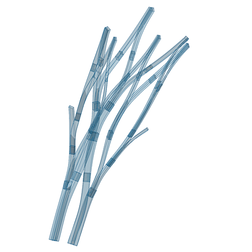
- This provides a suitable cross-over between the first two stages and a finer beam model. Figure 4 shows the population of each module with dimensioned and oriented glulams, with the necessary overlaps and extensions for connections. Because of the earlier triangle model, relationships between modules – for continuity and joint connections, for example – are maintained. The sizing of the members is informed by the aforementioned network analyses and edge weightings.
- Figure 5 shows the end-result after all the clipping and joining of members is done. If you scroll back a few posts, you’ll see the difference between this and the earlier model is subtle but important. There is a finer control over each stage of the workflow here and the model is no longer a slave to the bifurcating unit. Also, the bifurcations aren’t a pure division by two anymore – this came from trying to form the bifurcating blanks in a single go, as a single piece: half of the lamellas went one way, the other half went the other way. This newer form revives the idea of iterative / recursive laminating and machining, and the mixing of existing production processes. More detail about that will hopefully follow soon.
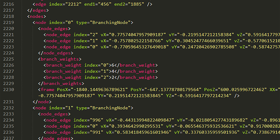
What I am trying to improve now is the way with which I generate each of these stages, record them, edit any of them by hand or through some other optimization process or the like, constrain variables at any level, and propagate those changes and constraints to the rest of the stages. I’ve started with a basic encoding of the higher levels, which also helps to minimize the working clutter, in that it can just be loaded from a file and doesn’t have to be associated with any lines or meshes that are always at risk of being moved, deleted, or forgotten. It’s bog-standard XML which also makes it easy to tweak by hand. What I’m sorting out now is a way to track and publish changes, and how to encode the lower levels which become increasingly volatile, being as their very existence is reliant on the higher network topology, and is at the mercy of any changes or disruptions there.
The last part of this rant concerns the actual production data and how that is now managed. There is sometimes a propensity to automate as much as possible, keep all things in a single model, and to always have constant real-time updates of the finished output. In my experience, this becomes dangerous where production is concerned. The fragility of a live model means that changes can be totally disruptive, in the sense of changing parts that are either already finished or in production, which generally does not play well. What the above ‘ecology of models’ also needs is a way to ‘lock’ aspects which are already made or are on their way to the machine.
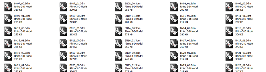
Anyway, the production files are all exported individually and with all necessary machining surfaces labelled, named, layered, etc. This also makes it easier to focus on the piece at hand during production, without being distracted by the chaos and confusion of the whole project model. It also makes it easier to tick them off the list once they are done.
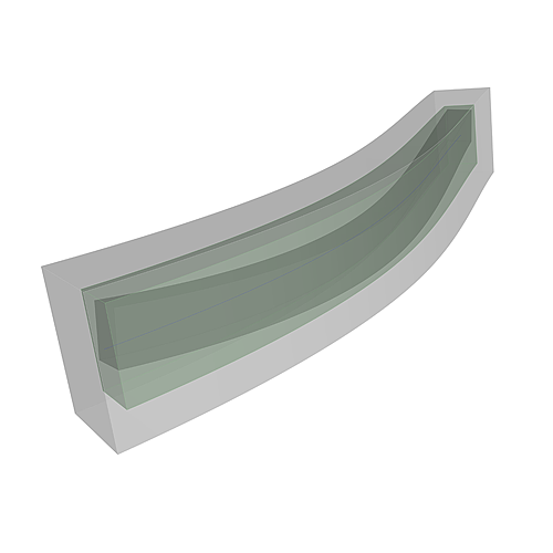
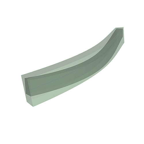
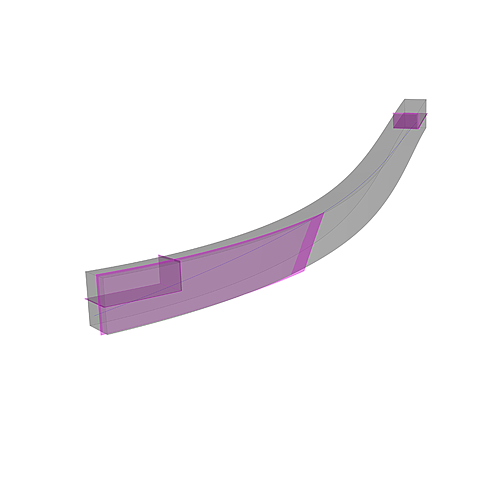
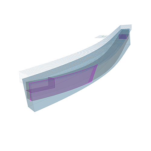
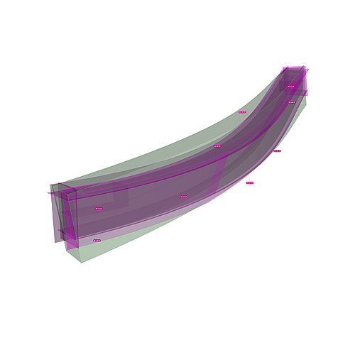
Below is an example of an exported workpiece. Figure 1 shows the blank (green), accompanying safe zone around the blank (outside grey) which is used to program safe retracts and rapids between machine paths, and the darker center is the ‘pseudo convex hull’ of the target beam, which is to say, the main surfaces of the beam without any joint details or other features. Figure 2 shows the single-curved blank and the beam, which is double-curved (remember the bit about decoupling these?). The waste concern becomes very visible here: all the lighter green space around the beam is to be machined away. Figure 3 shows all the machining surfaces (surfacings, joint details, the surface for laminating the two halves together) with associated normals and labels. Figure 4 shows just a couple of the feature surfaces and simple joint details. Figure 5 shows a machining strategy for surfacing the top face of the beam.