Blumer-Lehmann visit – Feb. 13-18
ESR2- INTEGRATING MATERIAL PERFORMANCE
AUTHOR: Tom Svilans
February 23, 2017.
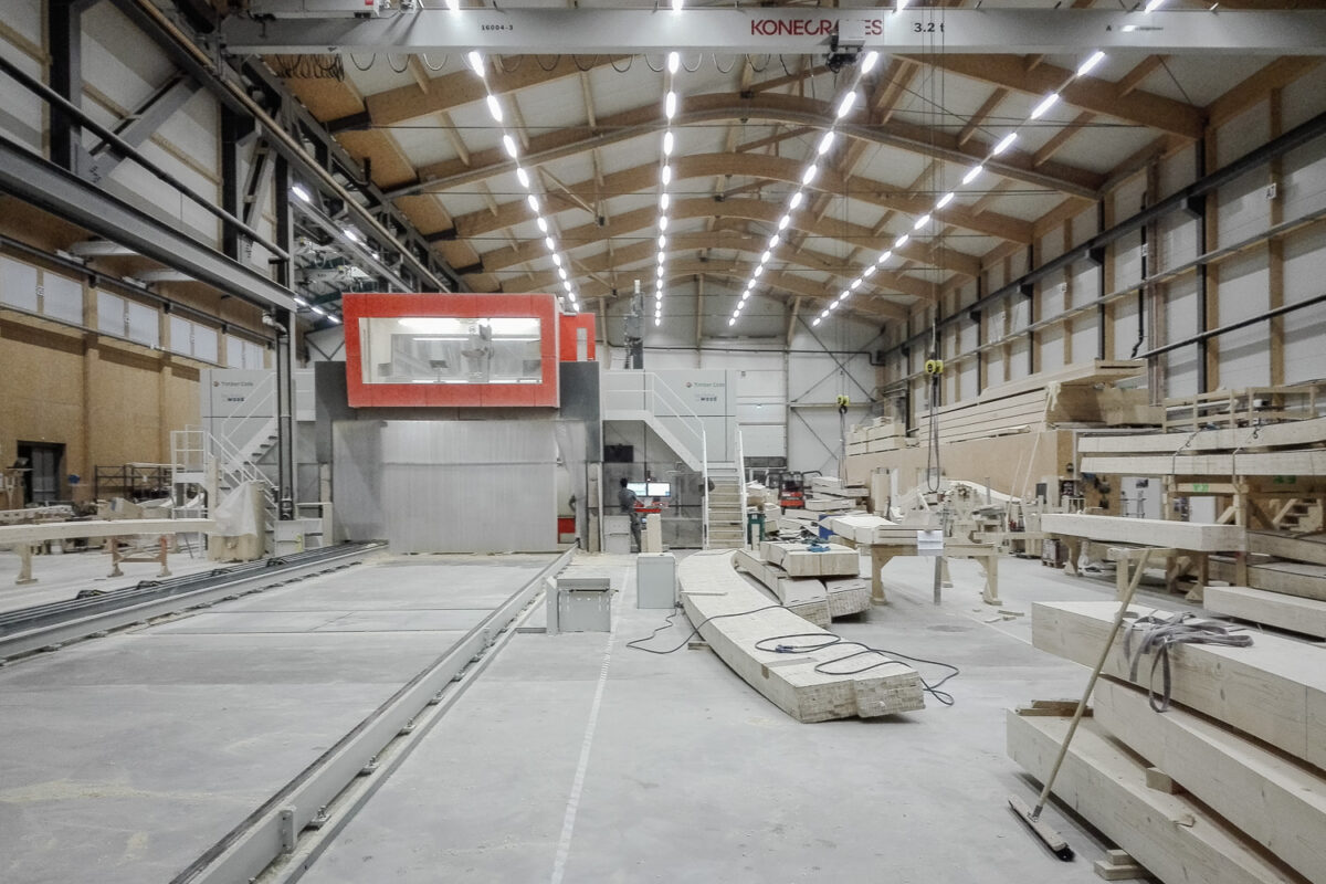
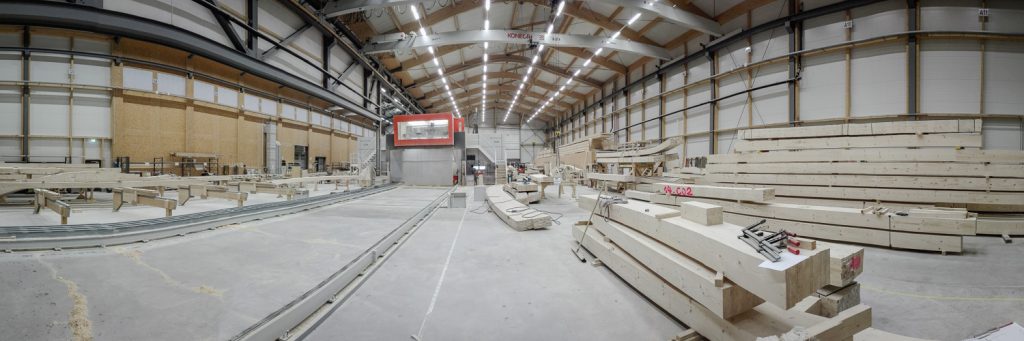
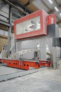
As part of my secondment at Blumer-Lehmann, I went down to visit Kai and the TW-Mill team and production facility, nestled in the Swiss countryside in Gossau, St. Gallen.
This week was devised as a ‘problem formulation’ phase, where we looked at the tools, interfaces, and knowledge necessary to begin to integrate laser sensing tools within the production of free-form glulams. This set the stage for an implementation phase later this spring after the first-year colloquium, which will focus on actually carrying out the installation of laser sensors on the main timber mill. In a range of escalating scenarios, this new sensing capability will be used to ensure the validity of the glulam blanks when they are first loaded before machining, and eventually to measure the workpieces during the machining process, and adaptively adjust workplanes and feature positions to account for workpiece deformation. The ultimate goal is to arrive at a kind of ‘soft fabrication model’ which has allowances for change and deviation in the fabrication process. This would be the starting point to address the questions of how this type of fabrication model can then re-inform broader design processes and lead to new and dynamic modes of design and industrial production.
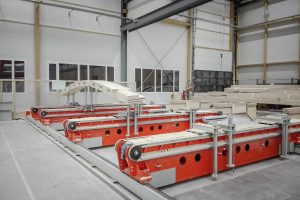
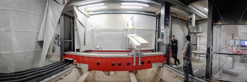
Very interesting to lurk and watch the full-on production on a day-to-day basis. What was particularly interesting was some of the informal aspects around how the place operates, how problems are dealt with, and how the various teams and people interact.
For now, preparation for the first-year viva and Innochain colloquium has taken over everything, as well as trying to push the demonstrator fabrication a little bit further. At the same time, looking towards the second part of this secondment, I have been working out the specifications for the sensor integration, talking with some suppliers, and looking into different systems. One of the problems that the implementation faces is the lack of an electrical interface within the machine spindle – and running wires around the inside of the machining enclosure would be way too risky – so any sensor head that is mounted on the spindle has to be battery-powered and wireless. As such I’ve been looking at wireless systems such as industrial Bluetooth or RF, which would allow the head to chat with the controller over a standard serial interface. I’ve ordered a couple of XBee modules to play with during breaks in writing, so hopefully I can produce a mock-up with the sensors and tools we have here at CITA before getting started on the real thing next month.
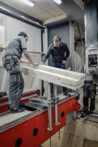
The other thing that was observed while in Gossau was the time it takes to ‘re-find’ a blank on the milling bed after it has been accidentally moved or become uncalibrated in some way. At the moment, this takes a lot of manual adjustment, moving the tool to various points and manually measuring distances and offsets. Back when I was working at the Bartlett, Jonny Martin and I did a small proof-of-concept project which used a motion-capture system in conjunction with a robot to track the deformation of laminated veneers.
![]()
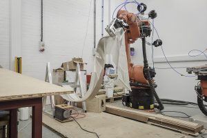
This allowed us to simply stick on some reflective stickers or little tracking spheres onto the surface of the laminate and get the spatial coordinates of each marker with a very high accuracy – within a couple tenths of a millimeter, usually. The great thing about this sort of system is that it’s compact and non-disruptive – just an array of cameras set up around the volume of interest and some adhesive markers.
This raises the possibility of an alternative / complementary system within the TW-Mill that could use markers placed on the spindle and the glulam workpiece to monitor the location of each point in real-time. Knowing where the blank is supposed to be, and seeing where the markers – spatial coordinates on the surface of the actual blank – actually are could make comparison and locating very easy… at least in theory. Anyway, I’m trying to see if I can borrow an Optitrack system to play with while I am down there next month.
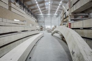
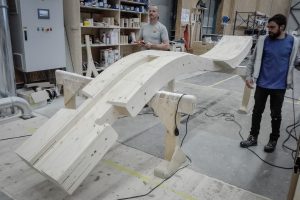
Now for a little bit of scenery…