Experiments 01

ESR2- INTEGRATING MATERIAL PERFORMANCE
AUTHOR: Tom Svilans
September 22, 2016. Some visual tests, follies, and development snapshots from the last couple of months.
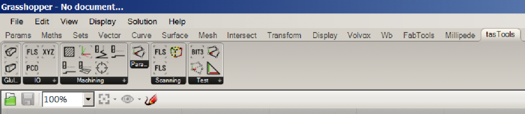
The software tools are accumulating as a pair of libraries – one in .NET, the other in C++/CLR – and some small peripheral utility apps as a way to keep all changes in one place and track them with proper version control (Git, in this case). Development has been focused on a few things:
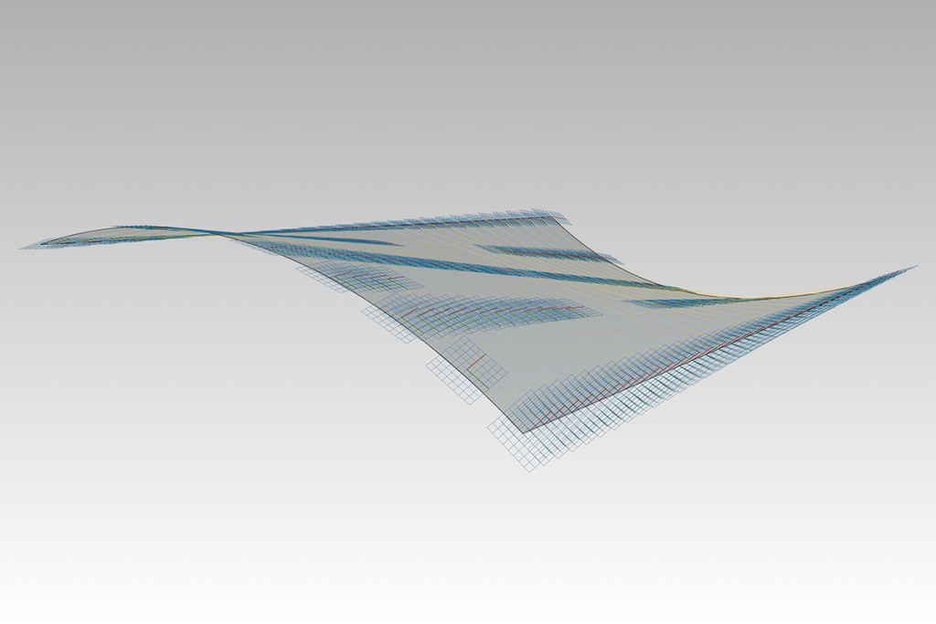
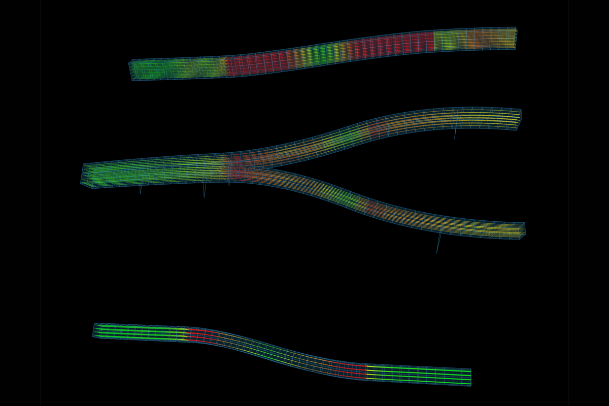
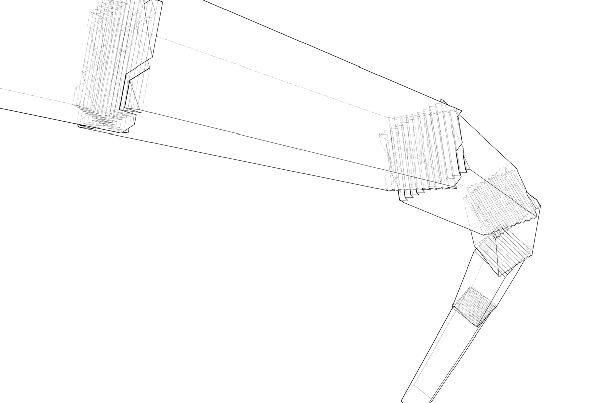
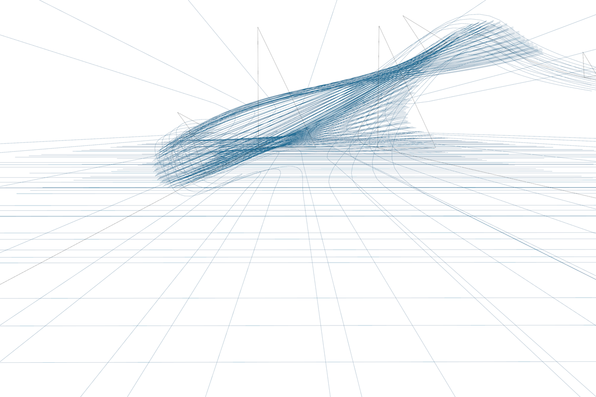
First, breaking a laminated timber assembly up into individual lamellas allows us to check things such as bending limits and orientations for different lamella sizes and placements, on top of analyzing the assembly as a whole. This also lets us start to play with the internal organization of the laminations: whether they are all aligned, cross-laminated, etc. The introduction of dynamic solvers on this level can also inform our formwork and forming process by revealing where the major forces are during forming, perhaps leading to leaner and more tailored formwork for different laminations.
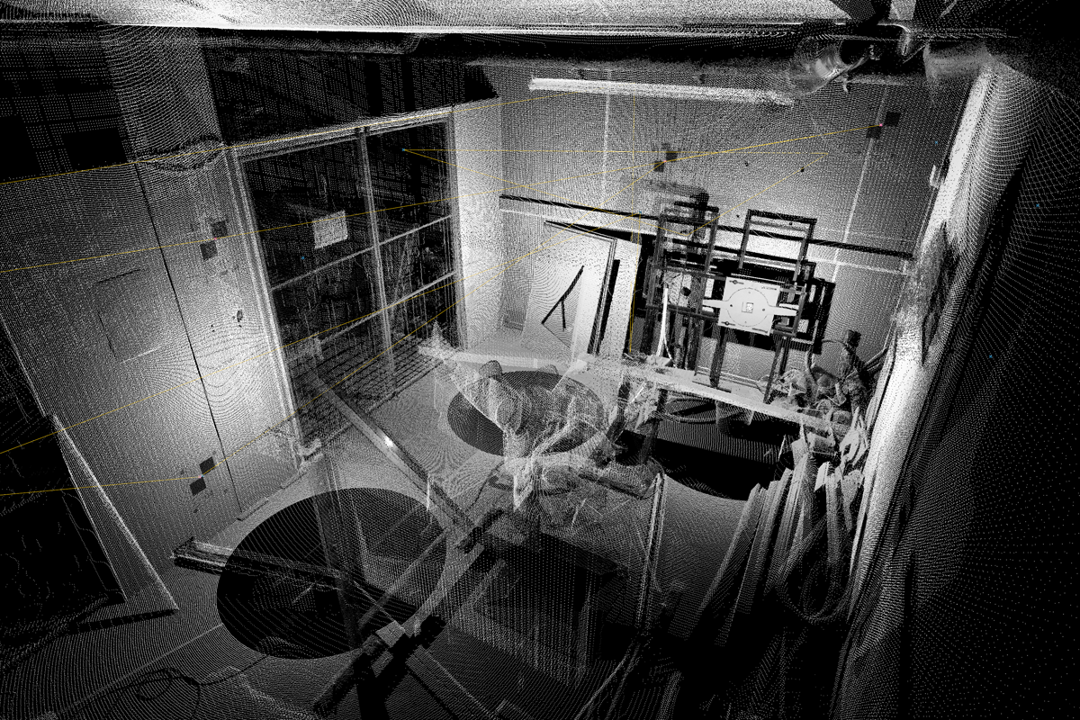
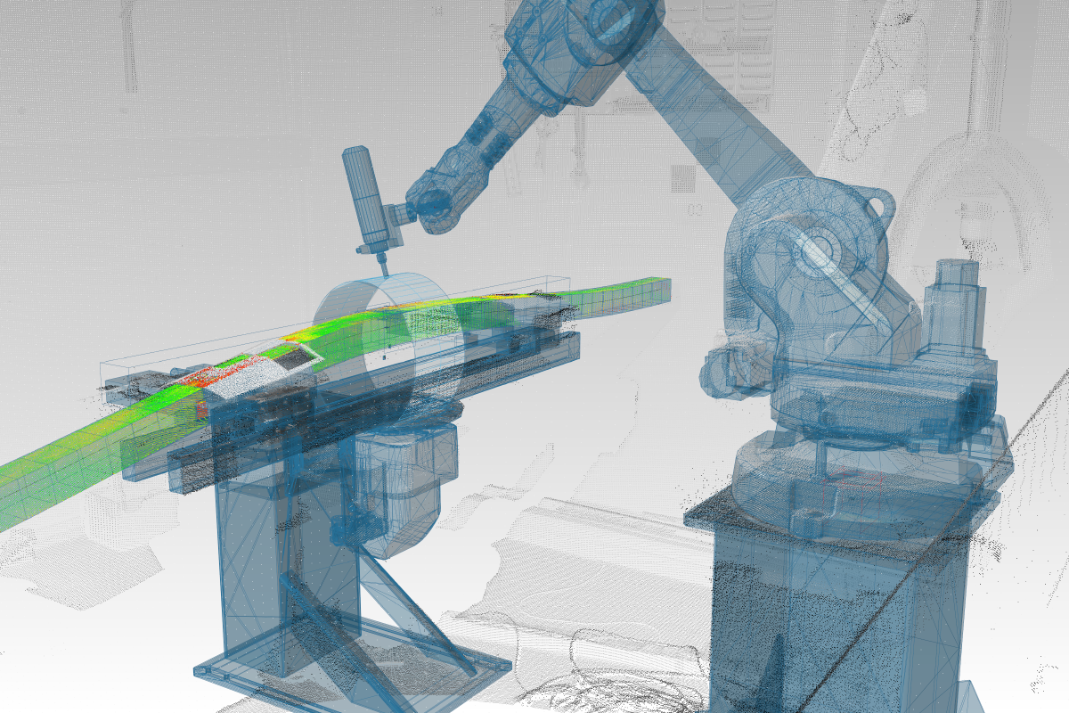
Second, the integration of scanning for verification and locating has been fleshed out by porting some PCL and OpenCV methods to .NET and writing a few little utilities in native C++ to handle menial tasks such as scanner communication, scan file conversion, batch processing, etc. Basic ICP and a hopefully more efficient target-based ICP have been implemented with PCL. The target-based variant still relies on manual target identification and only uses data within a specified radius around those targets to align scans. Automatic feature recognition exists, however since often much of the content of the point cloud will be changing between scans, there needs to be a certain amount of control over which parts of the scan are used to register, especially when sawdust starts flying. Of course, this would be a lot easier if the scanner always stayed fixed, so its frame of reference relative to the cell would stay constant. Anyhow, I am looking at some automatic checkerboard or QR code detection using OpenCV or the like.
What remains is to implement a more robust way of aligning mesh / NURBS models to the actual scan data, especially since the scan data will almost always be incomplete. Most techniques I have found rely on generating a point cloud from the model surface or using its vertices / control points as a point cloud, though there must be one that uses the surface and normal data directly.
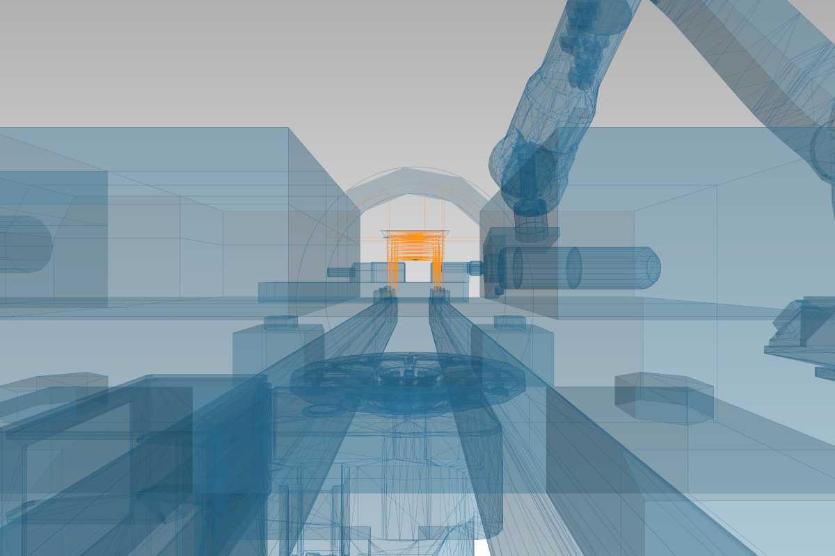
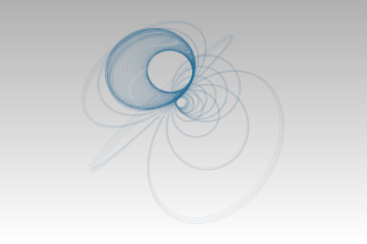
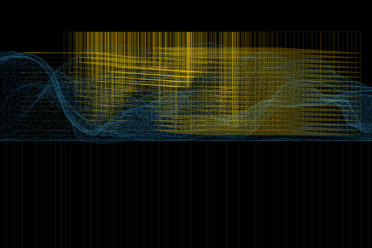
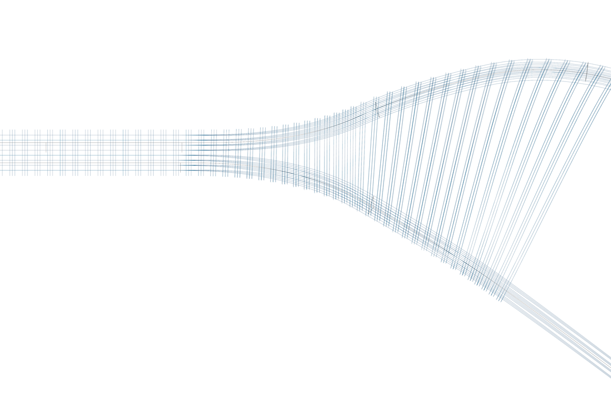
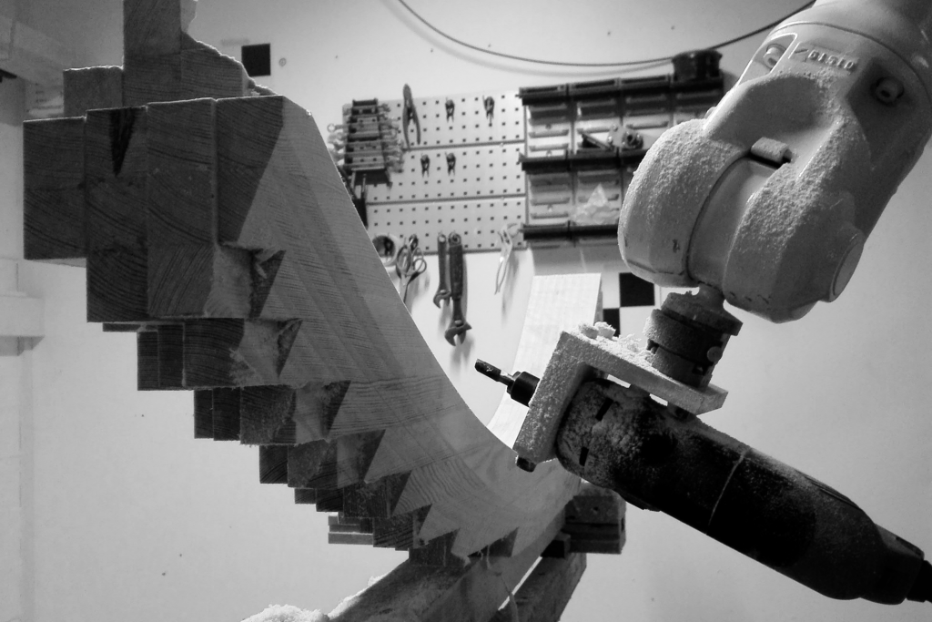
Third, several toolpath generation tools have been fleshed out and these were successfully used in a very recent workshop here at CITA with the new batch of Masters students. Much of the curve clipping and offsetting is handled by the amazing Clipper library. At the moment, they allow for fast pocket, profile, flowline, and area clearance generation from arbitrary inputs, so perhaps there is the opportunity to drive toolpath generation with higher level data. All of this toolpath and robot programming has necessitated the creation of a new Oriented Polyline data type, which is effectively the exact same as a Polyline in Rhino, except with planes instead of points as vertices. In fact, it inherits from most of the same base classes, so it works exactly the same way. This allows us to keep orientation information with the toolpath, so alongside curvature, we can keep track of twist, which is also really useful for the glulam / fibre modelling in the first point.
More updates will come soon, including a whole essay about why (precise) tool calibration is hard.